grease trap diagram
Create a grease trap diagram. Without Absorber 475538 1 2 Grease Trap Assm.
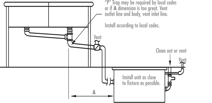
Installation Diagrams Rockford Separators
Creating a grease trap diagram can help you keep track of the traps.

. Grease traps are installed as part of the plumbing at food service facilities such. ReWa Grease Interceptor Detail QUESTIONS. Not to scale 24-inch opening to accomodate a 24.
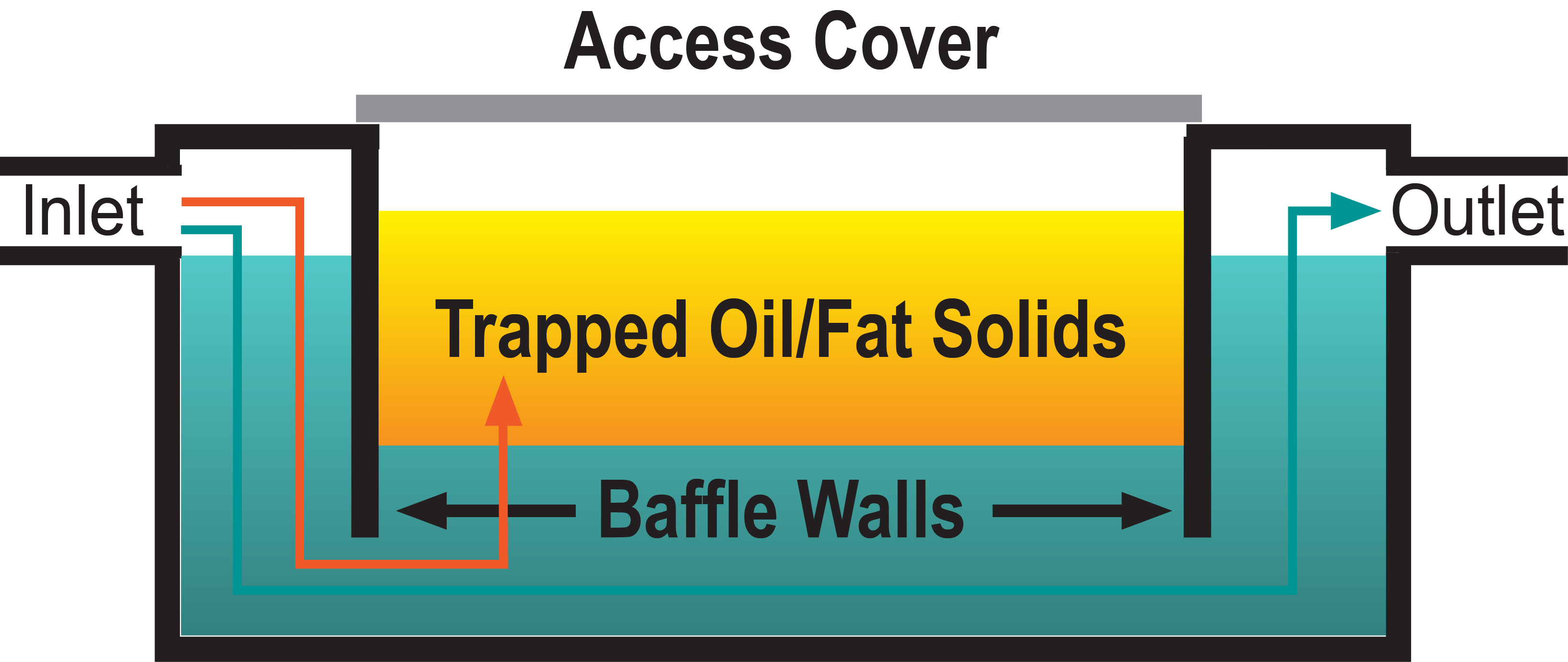
Grease traps are to be installed at a minimum distance of 10 ft. 25 GPM Grease Trap CAD Drawings Zip file 25 GPM Grease Trap Low Profile CAD Drawings file 35 GPM Grease Trap CAD Drawings Zip file 50 GPM Grease Trap CAD Drawings Zip file XL. In general grease traps contain baffles with baffles.
Water temperatures must be less than 120. If left unchecked fats oils and grease solidifies and sticks to the. Grease traps and the contributing plumbing configuration must be approved by the City of Bloomington Utilities Department prior to installation.
Register your Big Dipper. A grease trap is a device that separates grease and solids from wastewater before it enters the sanitary sewer. Shipping Returns Policy.
Kim McDonald ReWa 864-419-7251 or Keith Moore ReWa 864-419-7051 Note. Grease Trap Installation 1 Parts List per diagram Number Description Quantity 1 Grease Trap Assm. With Absorber 476085 1 3 Flat.
Grease Traps What are grease traps. Once youve removed the lid take note of where each part of the grease trap is located. For more information please contact the.
Internal Under the Sink Grease Trap Diagram Vent Pipe Must be lower than sink drain Flow Restrictor Grease Trap. 46 25 23 - Grease Traps - CAD Drawings CAD DOWNLOAD SAMPLE CAD COLLECTION Search for Drawings Browse 1000s of 2D CAD Drawings Specifications. How a Grease Trap Works see diagram following table A Flow from four or fewer kitchen fixtures enters the grease trap B An approved flow control or restricting device is installed to.
Find Your Grease Trap Code. The outlet pipe has a tee that allows the internal discharge to be located within. Grease traps are designed to stop fats oils or grease from entering the sewer lines.
Grease Trap Pit is a precipitation system designed to trap grease and suspended sediment in industrial wastewater. From sinks and dishwashers to allow for adequate cooling of the wastewater. Grease traps usually consist of an underground watertight concrete tank with baffled inlet and outlet piping.
FLC SERIES AppROVED SINKS OPTIONAL p _ TRAP VENT AIR.

Img Commercial Sink Plumbing Diagram Interceptor
Grease Interceptor The City Of Fountain Valley

Trapping And Venting For Grease Interceptors
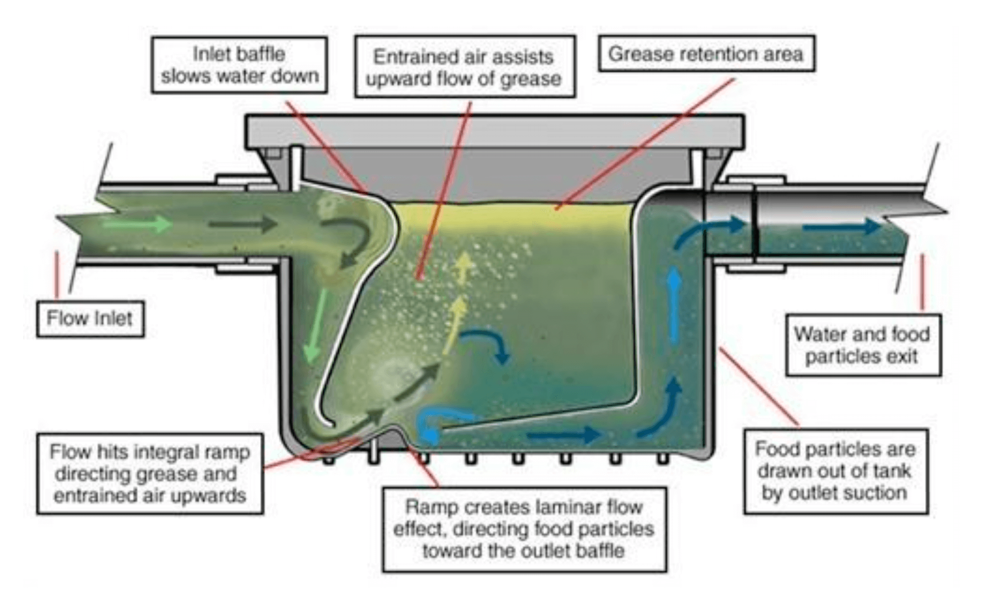
Fats Oils And Grease Disposal Capital Region Water
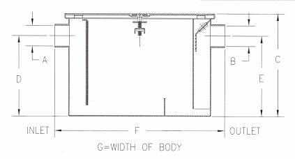
Grease Removal Systems Grease Traps And Grease Interceptors

Grease Traps Avilas
Hydromechanical Grease Interceptors James City County Va

3100 Litre Grease Trap W M Kiely Ltd Cork
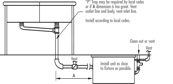
Installation Diagrams Rockford Separators
Grease Trap Cleaning Lees Environmental
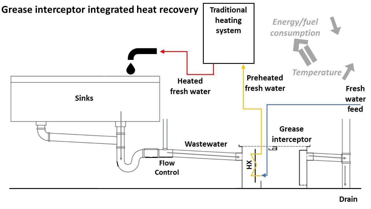
Recovering Heat Saving Space Grease Trap Integrated Heat Recovery Dwr Uisce
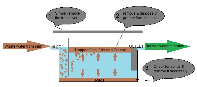
Grease Trap Diagram

Grease Trap Cleaning In Des Moines Ia Interceptor Services

Hydromechanical Grease Trap Inspection Gallery Internachi

The Dirty On The Grease Trap Septic Tank Grease Trap Service

10 Grease Trap Ideas Grease Traps Septic System

Grease Cleanup Removal Apollo Plumbing